- Domain Names
-
Want your very own domain? It's easier and cheaper than you might think!
- Web Hosting
-
Get your website up and running in minutes! Our packages start at just a few dollars a month.
- SSL Certificates
-
Protect yourself and your customers by securing your site with industry-standard encryption.
- IT Services
-
Downtown IT has friendly, professional, expert technicians who are ready and willing to solve even your biggest networking and IT issues.
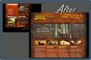
It is imperative to have a professional website to maintain a successful business. Your website can inspire trust, attract new business, and even forge relationships with customers.
Silentium Designs specializes in professional web development with customer convenience in mind. We know you want to be able to make changes yourself, so we offer our own Content Management System (CMS) to make simple changes easy. Add/remove photos, change text, prices, etc. in just seconds, saving you time and money.
Contact Silentium Designs today for a free quote — Click Here.